After seeing some other similar works on internet, I decided to try building a proofing box!
For building a proofing box, the following components are needed:
- a container
- an heat source
- a controller
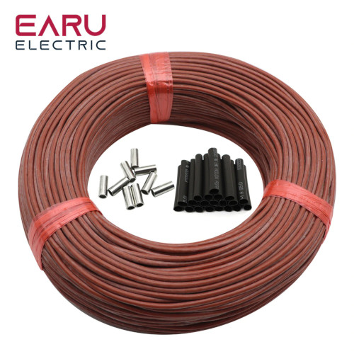
In my case, I decided to build a simple rectangular box as contaneir. As heat source I bought a carbon-fiber heating wire for about 6€. As specifications of the one I bought, it is a linear resistance of 33ohm/meter and the maximum supported power is 25W/meter.
Instead, as controller I picked an Arbuino Nano and some other components (see below for the complete list).
I will go into details of the building. I will follow the process I made. In retrospect, I can say that I made some errors, and I underline also them 😅. Let’s start!
The Box
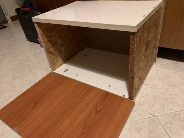
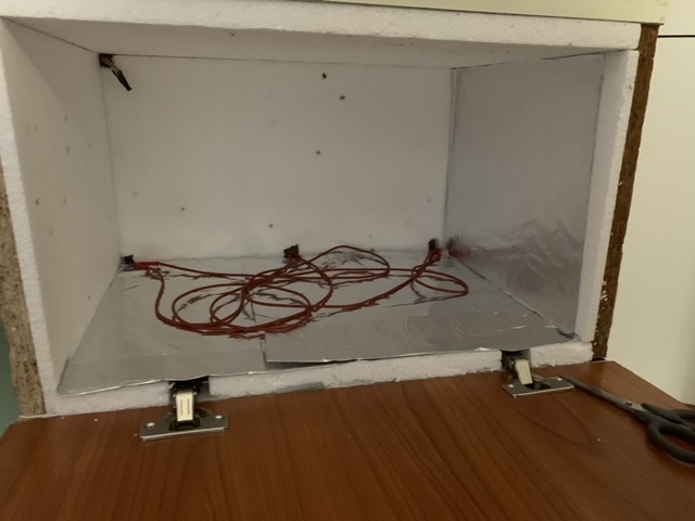
First of all, I found some chipboard panels, and I cut them in piecies in order to create a rectangular box, fixing them with screws. There are some holes and the cuts are not perfet, but they are recycled for some old forniture, so I’m quite satisfied with that. Here the result of the raw box:
After that, I start working on the eletrical and controll part.
Components
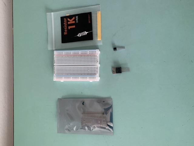
Here a list of the main components I used in that project:
- Arduino Nano or similar (I used a AZDelivery Nano based on ATmega328P Micro Controller)
- LM35 (temperature sensor)
- IRF540N (Mosfet NPN)
- 1K Ohm resistor
- some optional LEDs and resistors
- a 20V power supply (for the heat cable)
- a 5V power supply (for arduino)
Connections
Here a schematics with connections I made.
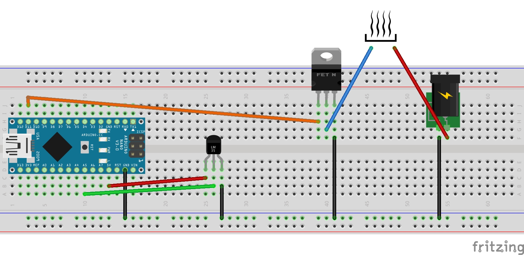
Note that the heating part is powered by a 20V power supply (a previous laptop power supply), while the arduino part is powered thourgh the arduino USB port with an USB charger (5V).
Arduino switches on and off the heat source using a Mosfet: rising the digital output connected to the gate port of the component, current is able to flow between drain and source ports.
In a first appent, I used a TIP 120 (darlington NPN transistor) instead of the Mosfet, with the only addition of a 1KΩ resistor between gate and arduino’s digital output. The result is similar, but due to the high current that flow thought that component, it become very hot, and I was at the suggested usage limit. So, I preferred to use the Mosfet.
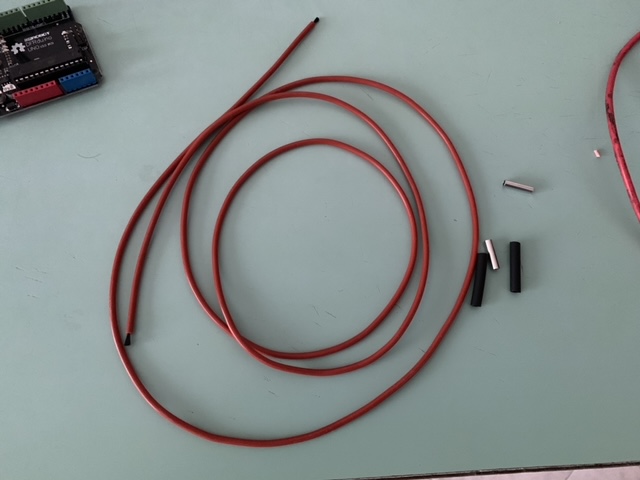
First of all, using a breadboard I tested all connections and the heat source. I started with 1 meter of heating cable, but I found that it was not eough to reach about 30°C iside the box. Then, I made some caulculus.
With a meter of heting cable (33Ω) and a 20V power supply, the theorethical electrical power is: \(i=V/R=20V/33Ω=0.606A\) \(P=V*i=20V*0.606A=12W\) That power is also ok with the maximum W/meter (25W/meter).
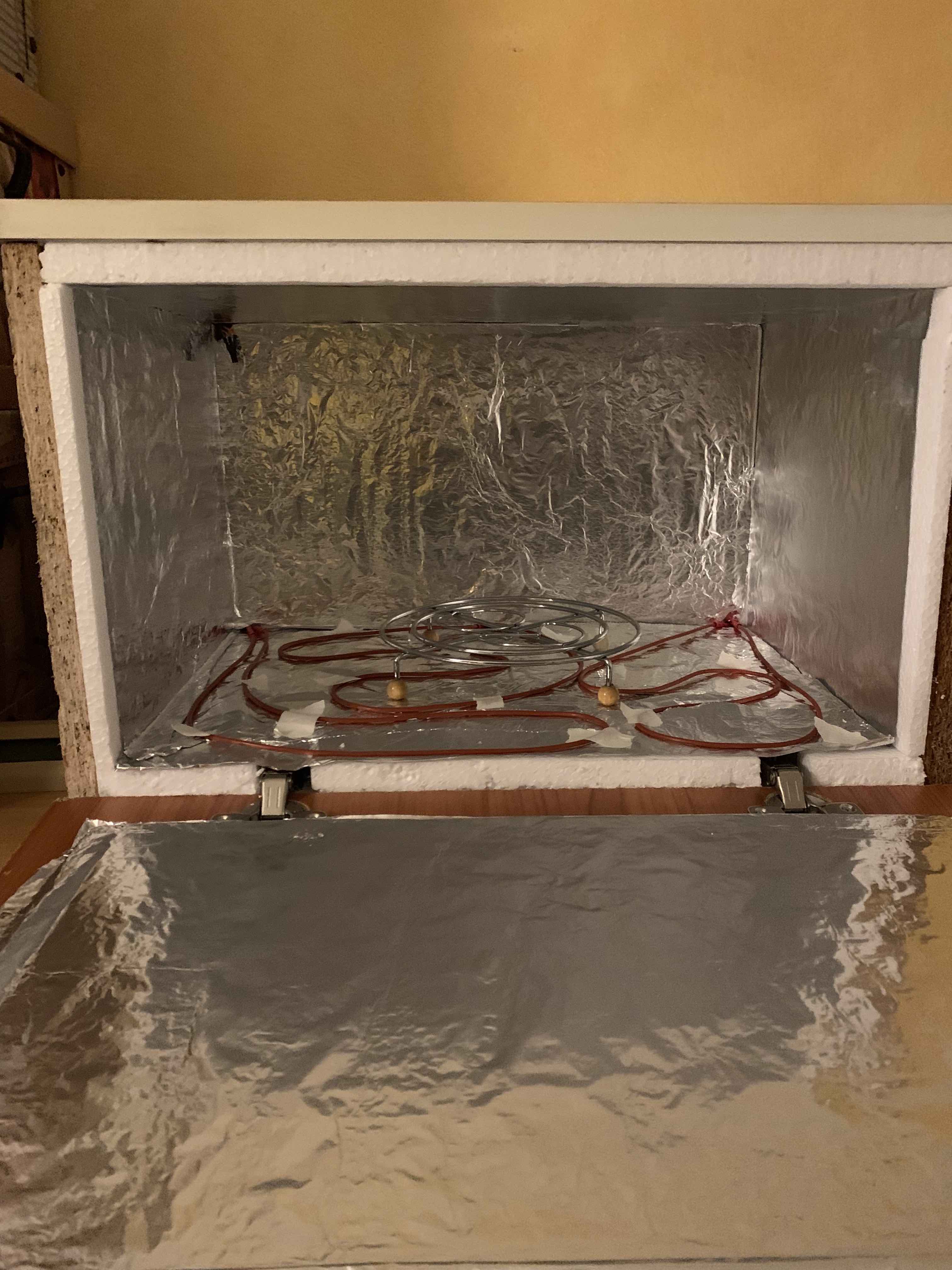
So, I decided to use 3 pieces of heating cable in parallel. In that way, I have about 36W of power. But, be sure that your powe supply can support more than 1.8A as output current.
Box thermal insulation
After I connected every electronical component, I got back to the box. Using some polystyrene panels and aluminum foil, I tried to inlulate the box as much as possible. Here some photos.
Arduino Software
After some experiments, I found that a simple control on the current temperature is enough. I tried a more complex solution (a simple PID control), but the result was not good as that naive solution, due to the very high latence of the heat cable (it takes 10-20 seconds to become hot).
Here the complete source code used.
| |
Some results
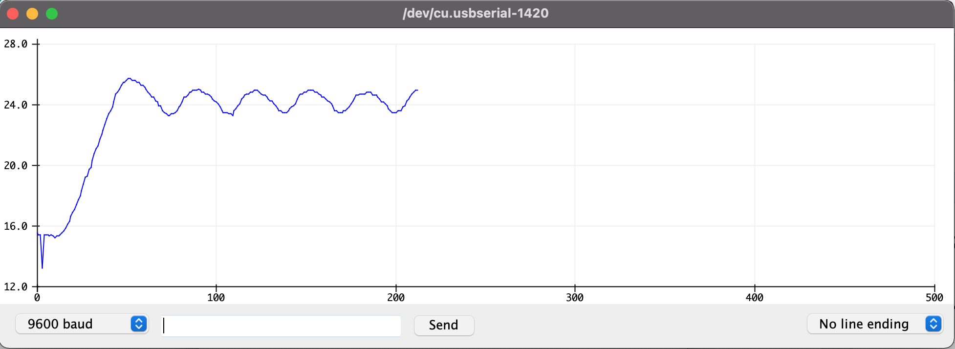
I made some tests with the Serial Plotter from Arduino IDE.
Here setting 24°C as target temperature:
Here setting 30°C as target temperature:
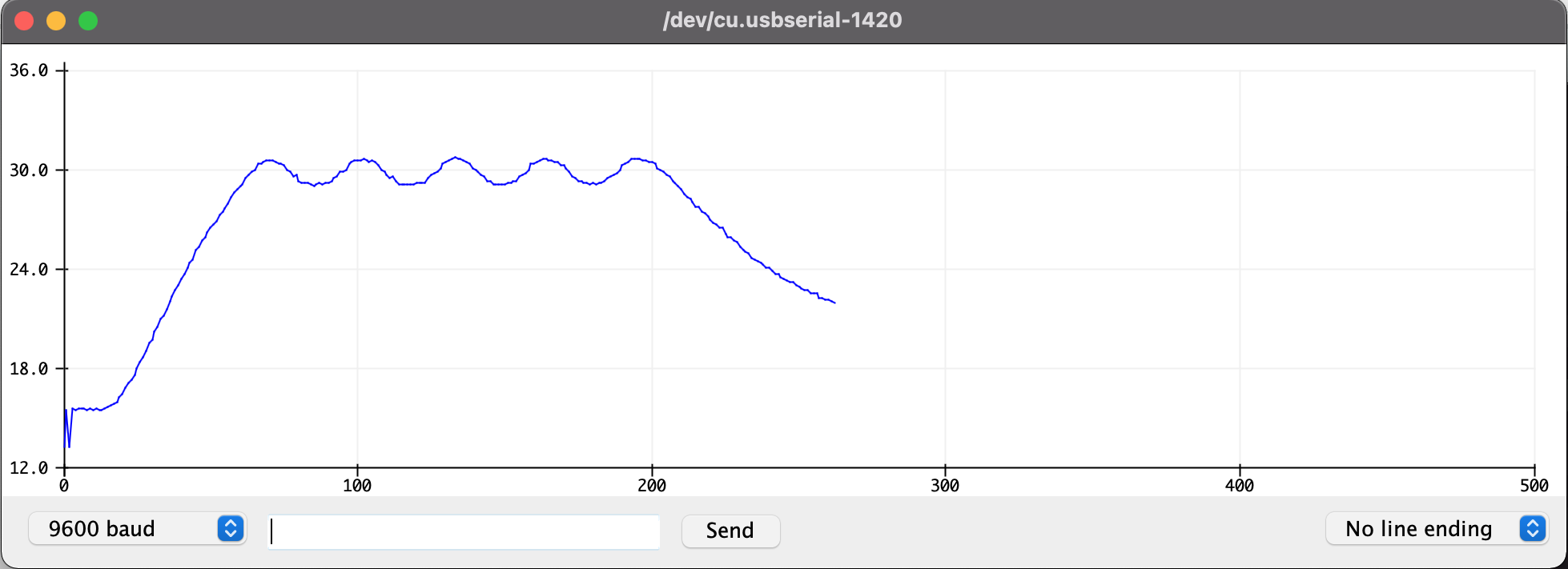
In the last one, after some minutes, I switched off the heating source’s power supply (at the end you can see the curve goes down).

Sources
Github: https://github.com/matteolel/homemade-proofing-box-arduino